
| All messages | Search Forums | Return to UrS4/UrS6/S2/RS2 |
| G22 Vehicle Speed Sensor (VSS) 012409191D Info - What it is and where the signal goes | |
|
Posted by: UrS4boy
(137)
on 2012-02-17 16:36:41
In Reply to: So my speedometer stopped working today posted by mrosario on 2012-02-17 20:43:33 |
Share | Report |
Several systems in the C4 UrS4/S6s (and the S2 and RS2s) rely on vehicle speed sensor (VSS) info. The details of this signal for a C4 AAN are shown below.
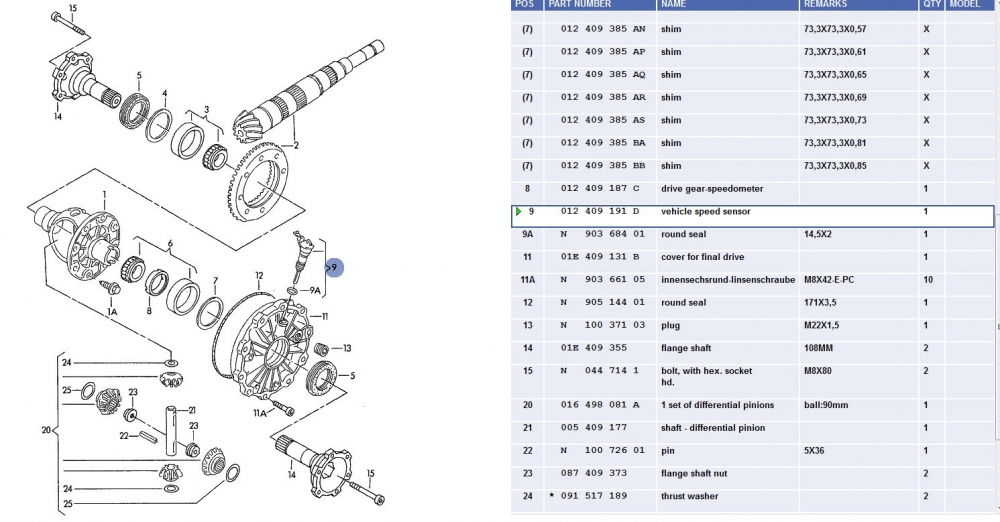
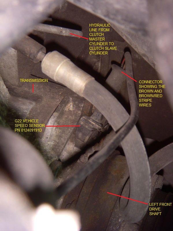
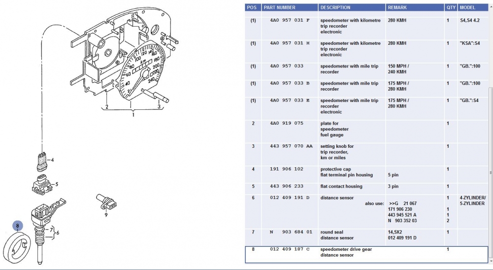
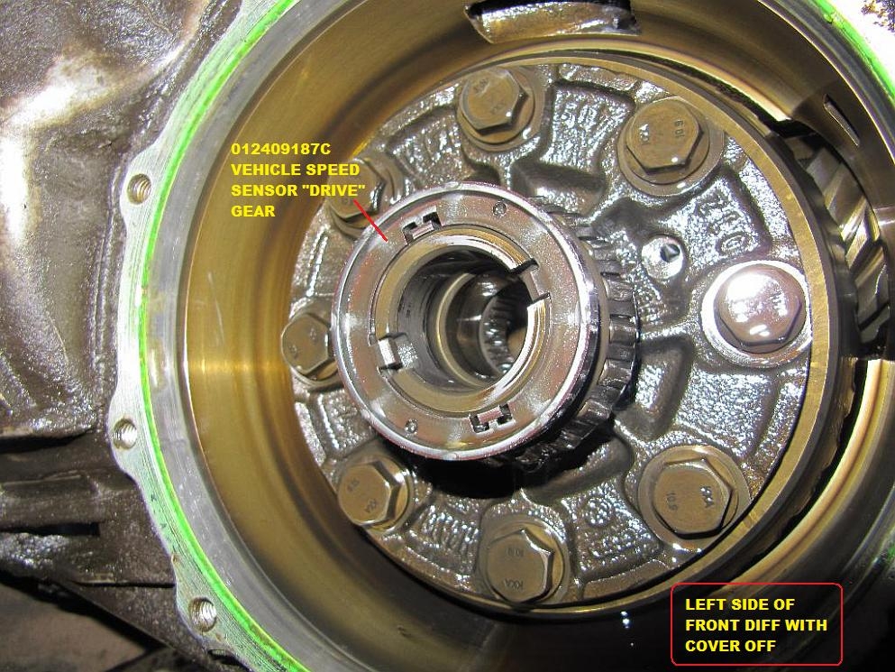
The vehicle speed sensor (VSS) is located on the left side (intake side) of the front differential, as shown below as Item 9. Item 8 is the magnetic drive gear that excites the G22 VSS which sends the signal to the speedometer (8 pulses per revolution)
Here it is in its OE location:
This generally what a new one looks like:

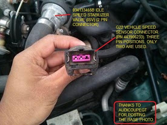
Note that the G22 has position for three pins but only two male pins are provided. The connector is a three pin connector, PN 443906233, Item 5 in the diagram below.
Here is a photo of the three pin connector. Note that only 2 female pins are provided (to match the two male pins on the G22 itself):
If your speedometer isn't working and you recently had clutch or transmission work, check that this three pin connector is plugged into the G22 VSS. Sometimes even the best shops mess this up and forget.
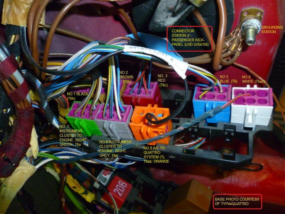
The three pin 443906233 connector only has two female pins and two wires, one brown (ground) and one Brown with a red stripe. The brown/red one the goes to T26/8 of the instrument cluster connector, via the red T6c connector in position 1 in Connector Stn. 2 (in the passenger side kick panel).(Addition Info about Connector Stn 2, T6c red connector and its involvement with the engine harness is found on p.12/17 of this Engine Harness - Passenger side pdf (download, save, and open)).
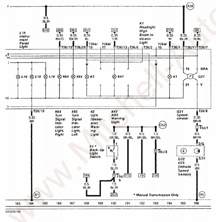
As suggested above, the G22 sends the signal to the G21 Speedo via a brown wire with a red stripe, entering the instrument cluster via pin 8 on the T26 (26 pin) instrument cluster connector. The white wire with the blue stripe, leaves the C4 instrument cluster via T26/7 and goes to track [64] where it branches, as listed in the table below. (The 3B S2 white/blue wire leaves the instrument cluster on T26a/18).
Here is a C4 diagram showing the G22 to G21 (speedometer) connection:
Here is a 3B S2 diagram showing the equivalent G22 to G21 connection:
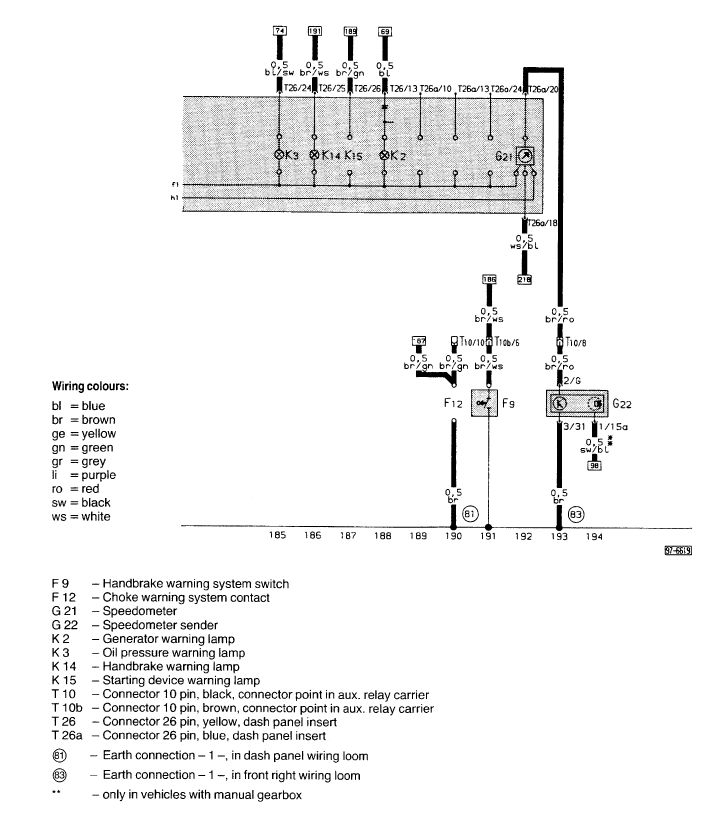
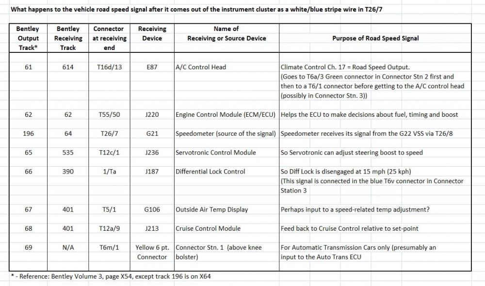
The signal leaves the C4 instrument cluster (speedometer) via pin 7 of the T26 instrument cluster connector as a white wire with a blue stripe. (Reference: Pg. X64 Bentley Vol. 3, Track [196]). This white/blue wire then heads to the ECU Pin T55/50 via the green T6a connector in Connector Stn. 2. As it does so it also splits and goes to six other locations, in addition to the T55/50 pin on the ECU connector. These locations are listed in the table below:
The 012409191D is very common and should be still available. GVAP shows it at around $29 HERE
Here is more info about the G22 and the speedometer drive gear.
European and ROW (non-American PNs):
NAmerican speedo PNs:
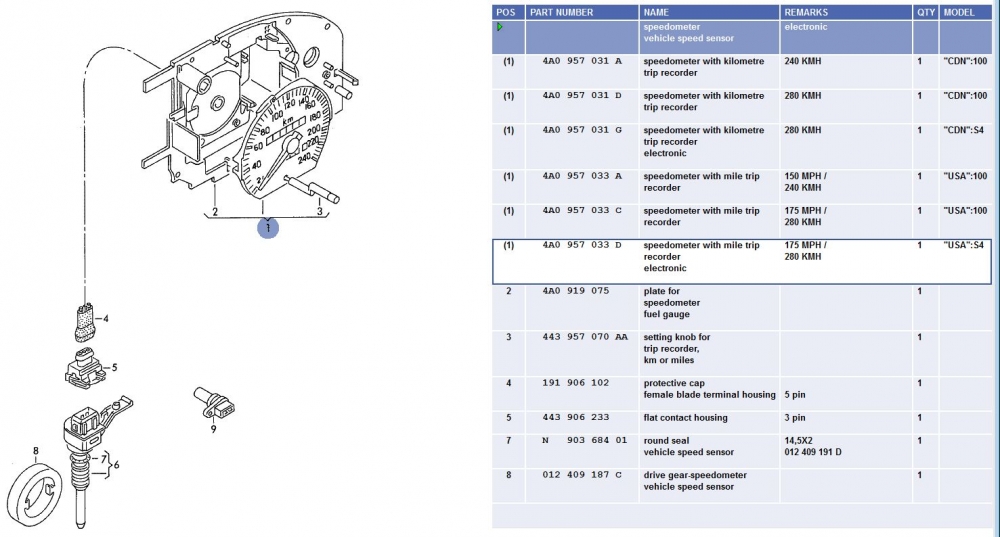
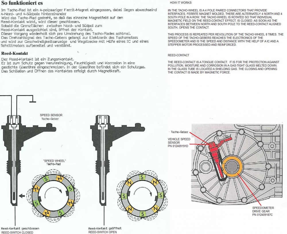
Here is how the speed sensor (reed switch) and the electromagnetic drive gear actually function.
Also got this from Aaron (SpeedingG60) on the S2Forum:
Recently (May 2013), Audi_F4i posted:
"(My)speedometer has been acting up for the past year or so. Installed a new G22 Vehicle Speed Sensor twice and even bought another Instrument Cluster off audifans to no avail. Decided to do a continuity test with a multimeter and was not getting continuity between the top and bottom of the T6c connector, speedometer 1/6 red/brown wire (red 6 pin connector located in the right hand kick panel).
(Base photo courtesy of Typ44, annotations courtesy of UrS4boy)
Pulled them apart:
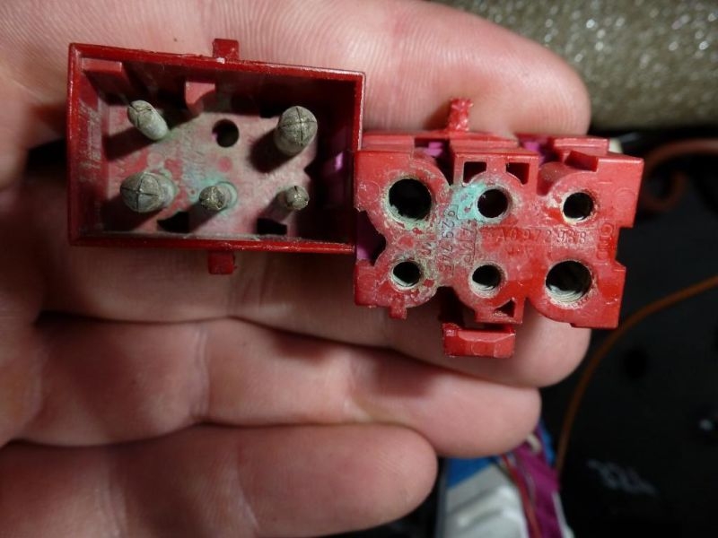
Photo courtesy of Audi_F4i
Cleaned them (the contacts) out with some electrical cleaner and some fine sandpaper on the pins to get the corrosion off. Plugged it back in and test for continuity and it passed. Drove the car and the speedometer now works....I think I might be getting water in there, going to check the rain drains next."
Connector Station 2 Information
Connector Station 3 Information
UPDATE:
The G22 Vehicle Speed Sensor gets its signal from the 012409187C sender ring. While the ring could fail, it is less likely to fail than the G22 012409191D sender. *IF* you have checked the traces on your instrument cluster to the G21 speedometer, and you have checked the continuity between the G22 and G21 through the various connectors *AND* you have replaced the G22 012409191D sender, then you probably have to check and replace the 012409191C sender ring. As "domas" on the S2Forum has suggested "You do not need to remove the box. Just remove DS axle, drain the oil and remove the side cover with CV flange."
The 012409191C sender ring, as available from ECS Tuning (or the dealer)
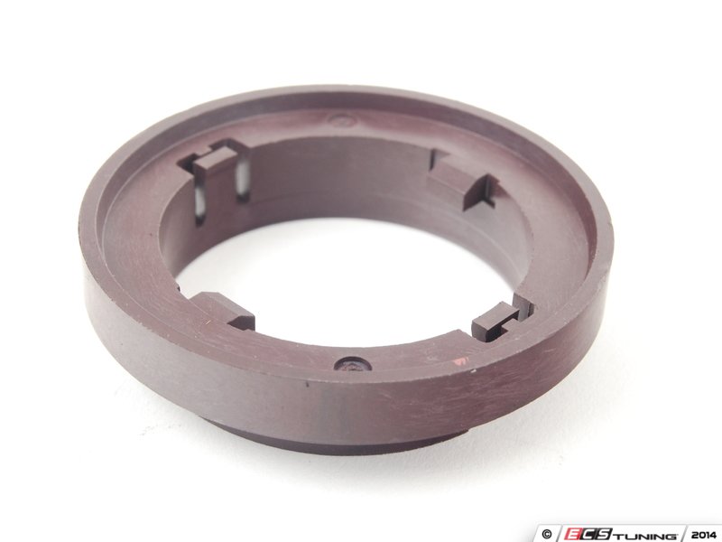
Here it is, exposed after removing the left front differential flange:
FURTHER UPDATE:
This is from dustovich in Edmonton, Alberta:
"Actually, we are all wrong about the speed sensor. Every revolution it pulses to 10 volts 8 times per revolution. Or every 1/8th a turn. So the standard oe tire size of 225/50-16 has a circumference of 78.06 inches or 1982.7mm. So between cycles you will have travelled 247.8mm or 9.75".
Visualized below as a square wave:
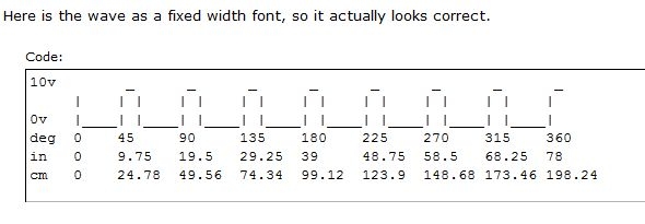
If we divide it out there are 4035.5 pulses/km. So now we know the distance measurement, now for speed. 1 km/h would be 4035.5 / 60 / 60 = 1.120972 hz and 100 km/h would be 112.0972 hz. So you can feed this into whatever you want to measure your speed.
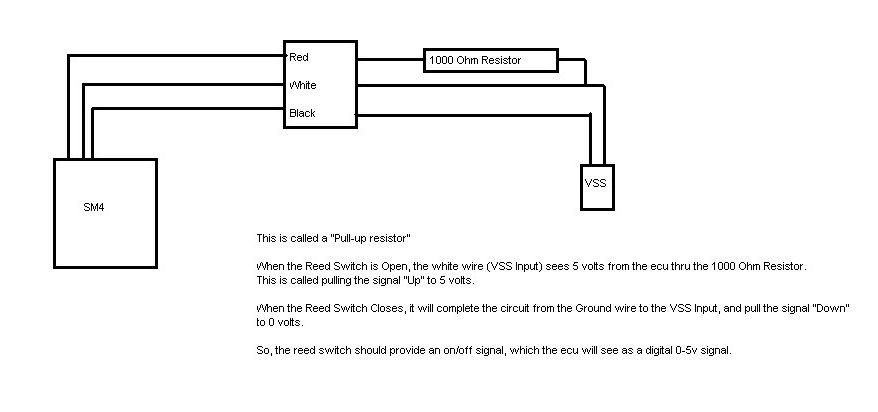
The easiest place to tap into the vss is the white blue wire on pin 1 of the blue plug in connector station 2 (passenger side kick panel). To see for yourself, put your meter on dc volts, put the positive lead in the connector and the other to ground/chassis and move the car slightly forward, you will see the pulses. It will even stay at 10v if you don't move the car when it is on the trigger.
The actual (EDIT:) reed switch signal goes directly into the gauge cluster and would require amplification to get the same signal as we see from this other location (google hall sender). The gauge cluster amplifies and rectifies the signal into a square wave and sends it to the ecu and wherever else it needs to go.
Hope this information is of more use then to just me haha."
REFERENCE: http://www.audiworld.com/forums/audi-original-s-cars-25/specifications-2834884/#post24364111 Post 11.
UPDATE: November 2015:
The equivalent of the red T6c C4 AAN connector for the B3/B4 chassis is the T10 in the auxilliary relay panel under the dash. Pin T10/8 to be exact.

The black connector in the lower right of this photo, beside the green T5 connector.
The vehicle speed sensor (VSS) is located on the left side (intake side) of the front differential, as shown below as Item 9. Item 8 is the magnetic drive gear that excites the G22 VSS which sends the signal to the speedometer (8 pulses per revolution)
Here it is in its OE location:
This generally what a new one looks like:
Note that the G22 has position for three pins but only two male pins are provided. The connector is a three pin connector, PN 443906233, Item 5 in the diagram below.
Here is a photo of the three pin connector. Note that only 2 female pins are provided (to match the two male pins on the G22 itself):
If your speedometer isn't working and you recently had clutch or transmission work, check that this three pin connector is plugged into the G22 VSS. Sometimes even the best shops mess this up and forget.
The three pin 443906233 connector only has two female pins and two wires, one brown (ground) and one Brown with a red stripe. The brown/red one the goes to T26/8 of the instrument cluster connector, via the red T6c connector in position 1 in Connector Stn. 2 (in the passenger side kick panel).(Addition Info about Connector Stn 2, T6c red connector and its involvement with the engine harness is found on p.12/17 of this Engine Harness - Passenger side pdf (download, save, and open)).
As suggested above, the G22 sends the signal to the G21 Speedo via a brown wire with a red stripe, entering the instrument cluster via pin 8 on the T26 (26 pin) instrument cluster connector. The white wire with the blue stripe, leaves the C4 instrument cluster via T26/7 and goes to track [64] where it branches, as listed in the table below. (The 3B S2 white/blue wire leaves the instrument cluster on T26a/18).
Here is a C4 diagram showing the G22 to G21 (speedometer) connection:
Here is a 3B S2 diagram showing the equivalent G22 to G21 connection:
The signal leaves the C4 instrument cluster (speedometer) via pin 7 of the T26 instrument cluster connector as a white wire with a blue stripe. (Reference: Pg. X64 Bentley Vol. 3, Track [196]). This white/blue wire then heads to the ECU Pin T55/50 via the green T6a connector in Connector Stn. 2. As it does so it also splits and goes to six other locations, in addition to the T55/50 pin on the ECU connector. These locations are listed in the table below:
The 012409191D is very common and should be still available. GVAP shows it at around $29 HERE
Here is more info about the G22 and the speedometer drive gear.
European and ROW (non-American PNs):
NAmerican speedo PNs:
Here is how the speed sensor (reed switch) and the electromagnetic drive gear actually function.
Also got this from Aaron (SpeedingG60) on the S2Forum:
Recently (May 2013), Audi_F4i posted:
"(My)speedometer has been acting up for the past year or so. Installed a new G22 Vehicle Speed Sensor twice and even bought another Instrument Cluster off audifans to no avail. Decided to do a continuity test with a multimeter and was not getting continuity between the top and bottom of the T6c connector, speedometer 1/6 red/brown wire (red 6 pin connector located in the right hand kick panel).
(Base photo courtesy of Typ44, annotations courtesy of UrS4boy)
Pulled them apart:
Photo courtesy of Audi_F4i
Cleaned them (the contacts) out with some electrical cleaner and some fine sandpaper on the pins to get the corrosion off. Plugged it back in and test for continuity and it passed. Drove the car and the speedometer now works....I think I might be getting water in there, going to check the rain drains next."
Connector Station 2 Information
Connector Station 3 Information
UPDATE:
The G22 Vehicle Speed Sensor gets its signal from the 012409187C sender ring. While the ring could fail, it is less likely to fail than the G22 012409191D sender. *IF* you have checked the traces on your instrument cluster to the G21 speedometer, and you have checked the continuity between the G22 and G21 through the various connectors *AND* you have replaced the G22 012409191D sender, then you probably have to check and replace the 012409191C sender ring. As "domas" on the S2Forum has suggested "You do not need to remove the box. Just remove DS axle, drain the oil and remove the side cover with CV flange."
The 012409191C sender ring, as available from ECS Tuning (or the dealer)
Here it is, exposed after removing the left front differential flange:
FURTHER UPDATE:
This is from dustovich in Edmonton, Alberta:
"Actually, we are all wrong about the speed sensor. Every revolution it pulses to 10 volts 8 times per revolution. Or every 1/8th a turn. So the standard oe tire size of 225/50-16 has a circumference of 78.06 inches or 1982.7mm. So between cycles you will have travelled 247.8mm or 9.75".
Visualized below as a square wave:
If we divide it out there are 4035.5 pulses/km. So now we know the distance measurement, now for speed. 1 km/h would be 4035.5 / 60 / 60 = 1.120972 hz and 100 km/h would be 112.0972 hz. So you can feed this into whatever you want to measure your speed.
The easiest place to tap into the vss is the white blue wire on pin 1 of the blue plug in connector station 2 (passenger side kick panel). To see for yourself, put your meter on dc volts, put the positive lead in the connector and the other to ground/chassis and move the car slightly forward, you will see the pulses. It will even stay at 10v if you don't move the car when it is on the trigger.
The actual (EDIT:) reed switch signal goes directly into the gauge cluster and would require amplification to get the same signal as we see from this other location (google hall sender). The gauge cluster amplifies and rectifies the signal into a square wave and sends it to the ecu and wherever else it needs to go.
Hope this information is of more use then to just me haha."
REFERENCE: http://www.audiworld.com/forums/audi-original-s-cars-25/specifications-2834884/#post24364111 Post 11.
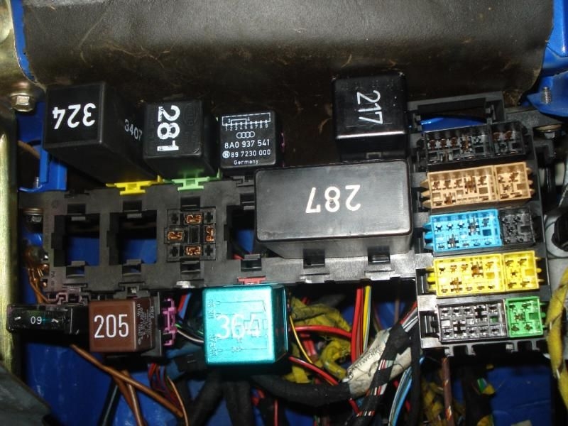
UPDATE: November 2015:
The equivalent of the red T6c C4 AAN connector for the B3/B4 chassis is the T10 in the auxilliary relay panel under the dash. Pin T10/8 to be exact.
The black connector in the lower right of this photo, beside the green T5 connector.

 -
-  -
-

You must be registered and logged in to post. Please select an option: |
| All messages | Search Forums | Return to UrS4/UrS6/S2/RS2 |
 Your Privacy Choices