
| All messages | Search Forums | Return to UrS4/UrS6/S2/RS2 |
| N75 Wastegate Frequency Valve (WGFV) location, function and PN info | |
|
Posted by: UrS4boy
(137)
on 2009-01-02 05:11:13
|
Share | Report |
N75 WGFV
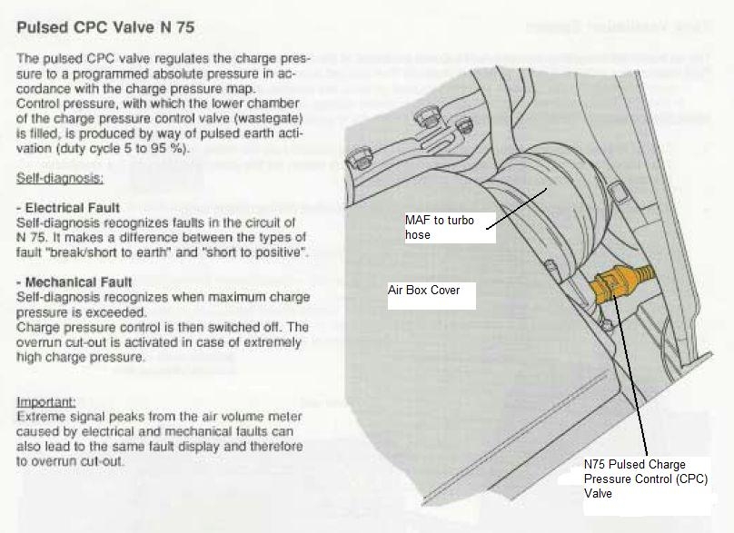
Our 20VT (3B, AAN, ABY and ADU) engines are controlled by a computer (ECU or Electronic control module (ECM)). This ECU controls boost pressure by either holding or dumping boost via a waste gate frequency valve (WGFV), the "N75", aka "pulsed charge pressure control (CPC) valve". The N75 is located near the front of the engine, near the MAF to turbo hose, as shown here:
Here is a photo of the N75 in place on an AAN, showing the red power wire and the yellow/red signal wire to pin T55/33 of the ECU connector (takes the N75 to ground, through the ECU, as controlled by the ECU):
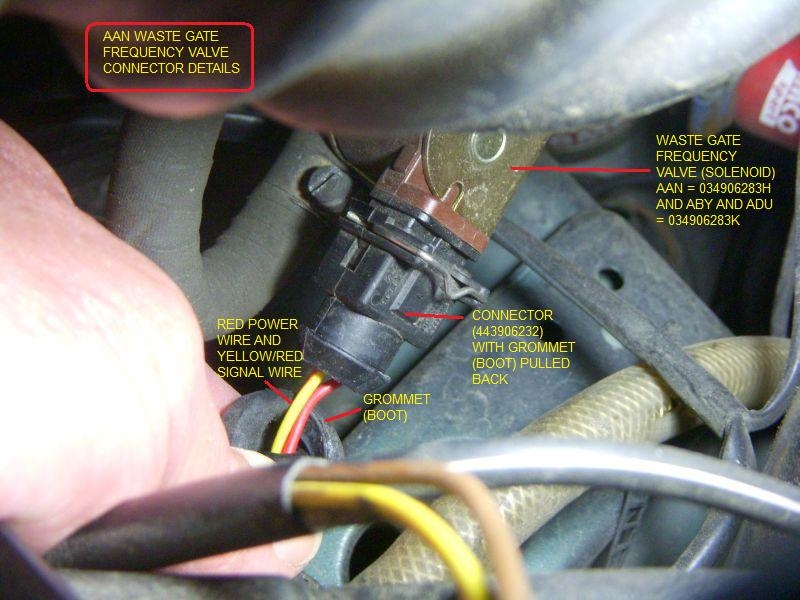
The red power wire comes from the S75 fuse/thermal fuse in the black fuse holder above the ECU. (This fuse also provides power to the N71 Idle Stabilization valve (ISV) and the N80 Evaporative Emissions Control Valve)
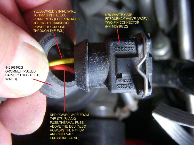
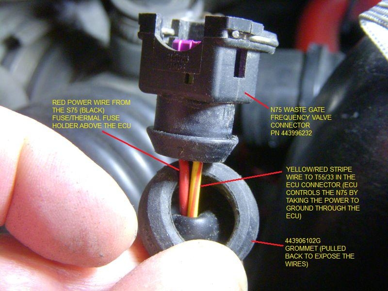
Here are some close-ups of the N75 connector, showing the connector number and the orientation of the red and yellow/red wires (the red power wire in position 1/2 and the yellow/red signal wire in position 2/2) (NOTE: For the ABY and ADU, the wires are blue/red power in position 1 and green/gold for the T55/33 connection in position 2/2):
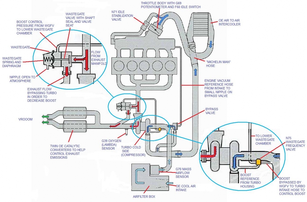
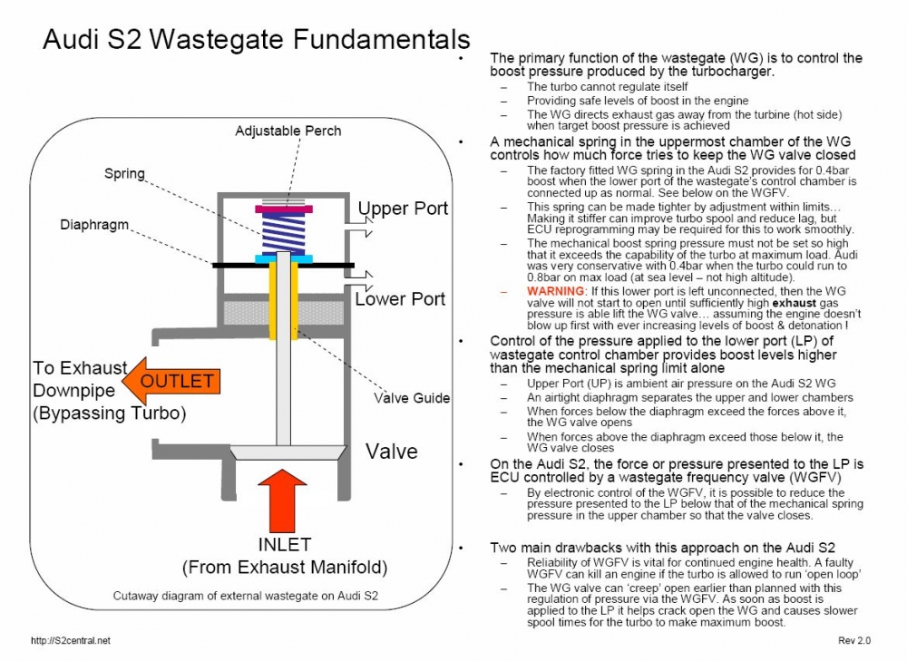
Here is a diagram that shows the mechanical interactions between the WGFV and the Wastegate.
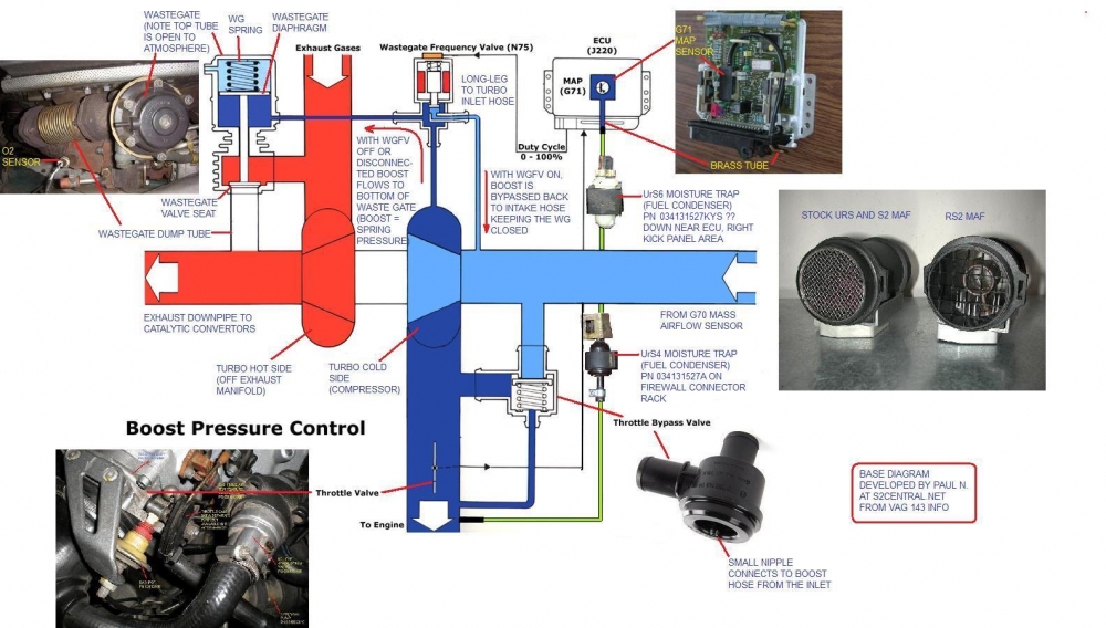
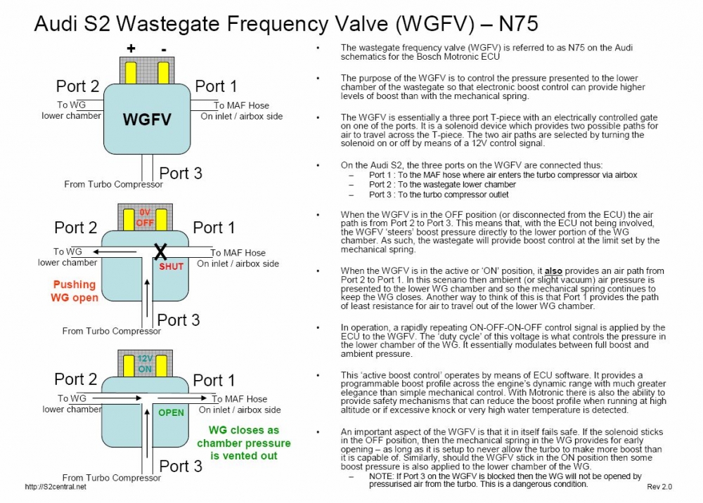
Here is a comprehensive diagram based on a diagram developed by Paul N. of S2Central.net, in turn, based on a VAG diagram, showing both the mechanical and the electrical (including ECU) connections to the N75 WGFV and how it interacts with the overall boost control system.
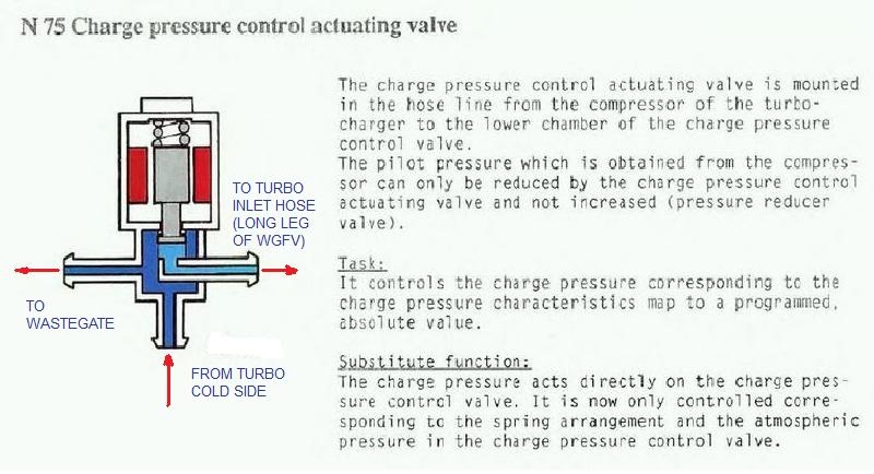
This is what VAG says about the N75:
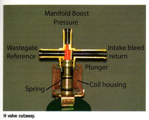
Here is another diagram, flipped vertically from the previous diagram, showing the the long leg on the right side of the diagram going to the turbo inlet hose:
Here is another diagram showing the orientation of the "legs" on the N75, this time in conjunction with the location of a Mechanical Boost Controller (MBC) that would limit the upper level of boost (trial and error setting). As above, the nipple coming out of the bottom of the WGFV solenoid goes to the turbo. The longer perpendicular leg nipple goes into the MAF to turbo hose. The remaining shorter leg perpendicular nipple goes to the Waste Gate. (I have one off my UrS4 in front of me - I am running the RS2 N75 which has the electrical connection plug differently oriented than the UrS4 N75 - but the important part is the orientation of the three nipples, not the electrical connector).
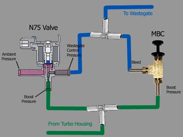
When electrically cycled, the N75 BYPASSES the wastegate, increasing boost.
Here is what our Marc S (of EFI Express fame) says about the WGFV and the connection of the long leg of the WGFV to the turbo inlet hose from the MAF:
"Under normal operation, air goes from the boost source to the outlet (wastegate). Thats a safety feature. If the valve is busted, it still opens the wastegate."
I know in the past, Marc has raised the red flag that you need to keep the WGFV connected to the wastegate, even if it broken because without it, there is no connection between the turbo and the wastegate to open the wastegate against the wastegate spring pressure. Under that scenario, the wastegate will not open and boost pressures will rise to (likely) destructive levels.
If you disconnect the WGFV from the ECU by pulling the electrical connector, the only boost you get is the amount provided by the wastegate spring. This can be useful as a "Valet" mode if you don't want somebody to wail on your engine when they drive it.
If there is any doubt as to which of the legs goes to the wastegate, blow through the bottom of the WGFV (the port normally connected to the turbo cold side housing) and feel which of the two remaining legs the air comes out. The one with the air coming out is the one that you connect to the lower port of the wastegate (the other is connected to the MAF to turbo hose). If you get air out of both of the other two legs, then the WGFV has failed and should be replaced.
Pertinent N75 PN's are:
034 906 283 J = stock 3B (in 200 20v and S2)
034 906 283 H = stock AAN (UrS4 and UrS6)
034 906 283 K = S2 ABY and RS2 ADU
Link to European Car N75 article on Skollie's server
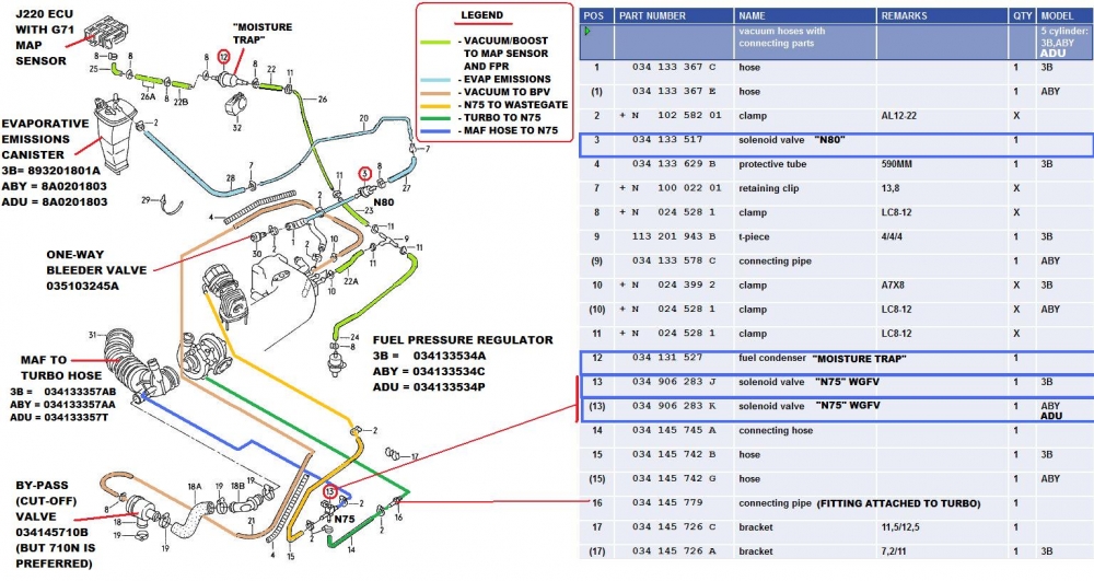
Here is how the stock AAN WGFV is plumbed up to the MAF, the turbo and the wastegate:
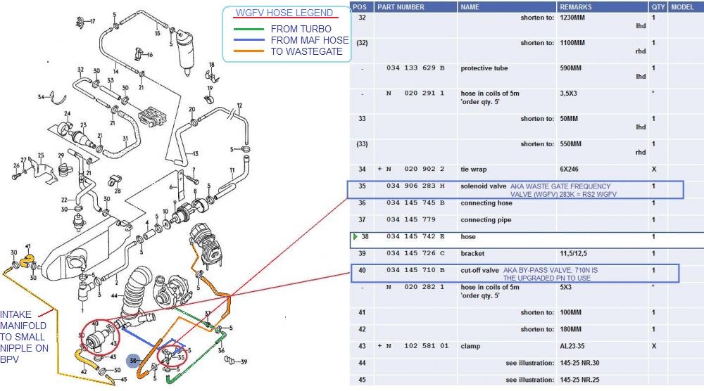
Here is the equivalent diagram (plus a few extras) for the 3B, ABY and ADU engines:
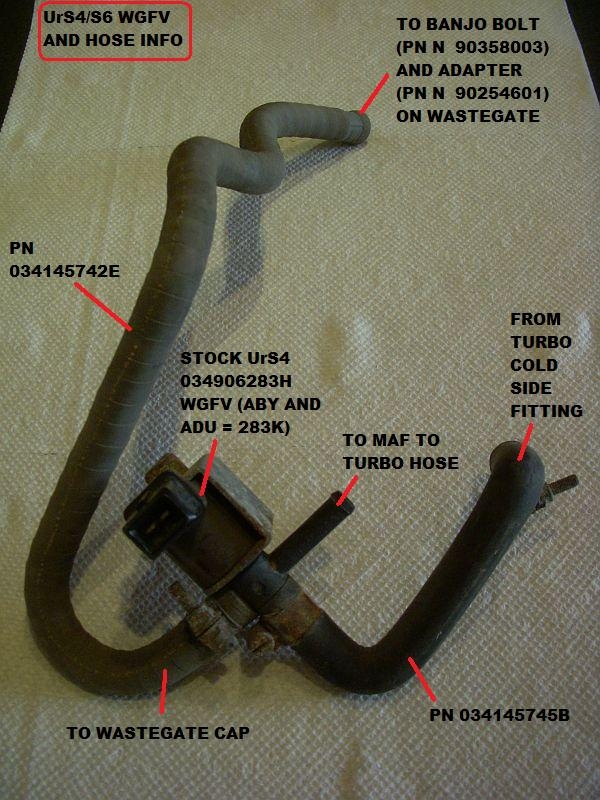
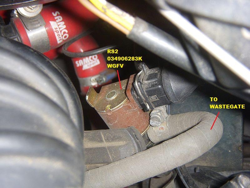
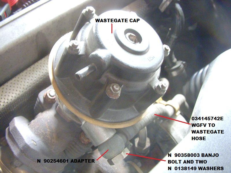
Here are some photos showing the hoses and connections:
Here are some Wastegate and N75 WGFV function explanations from Paul Nugent at S2Central.net:
and
Scott Mockry at his SJM Autotechnik website outlines an N75 test procedure that might be of use.
Thanks to those who posted the diagrams, photos, links, etc. used in this post.
Our 20VT (3B, AAN, ABY and ADU) engines are controlled by a computer (ECU or Electronic control module (ECM)). This ECU controls boost pressure by either holding or dumping boost via a waste gate frequency valve (WGFV), the "N75", aka "pulsed charge pressure control (CPC) valve". The N75 is located near the front of the engine, near the MAF to turbo hose, as shown here:
Here is a photo of the N75 in place on an AAN, showing the red power wire and the yellow/red signal wire to pin T55/33 of the ECU connector (takes the N75 to ground, through the ECU, as controlled by the ECU):
The red power wire comes from the S75 fuse/thermal fuse in the black fuse holder above the ECU. (This fuse also provides power to the N71 Idle Stabilization valve (ISV) and the N80 Evaporative Emissions Control Valve)
Here are some close-ups of the N75 connector, showing the connector number and the orientation of the red and yellow/red wires (the red power wire in position 1/2 and the yellow/red signal wire in position 2/2) (NOTE: For the ABY and ADU, the wires are blue/red power in position 1 and green/gold for the T55/33 connection in position 2/2):
Here is a diagram that shows the mechanical interactions between the WGFV and the Wastegate.
Here is a comprehensive diagram based on a diagram developed by Paul N. of S2Central.net, in turn, based on a VAG diagram, showing both the mechanical and the electrical (including ECU) connections to the N75 WGFV and how it interacts with the overall boost control system.
This is what VAG says about the N75:
Here is another diagram, flipped vertically from the previous diagram, showing the the long leg on the right side of the diagram going to the turbo inlet hose:
Here is another diagram showing the orientation of the "legs" on the N75, this time in conjunction with the location of a Mechanical Boost Controller (MBC) that would limit the upper level of boost (trial and error setting). As above, the nipple coming out of the bottom of the WGFV solenoid goes to the turbo. The longer perpendicular leg nipple goes into the MAF to turbo hose. The remaining shorter leg perpendicular nipple goes to the Waste Gate. (I have one off my UrS4 in front of me - I am running the RS2 N75 which has the electrical connection plug differently oriented than the UrS4 N75 - but the important part is the orientation of the three nipples, not the electrical connector).
When electrically cycled, the N75 BYPASSES the wastegate, increasing boost.
Here is what our Marc S (of EFI Express fame) says about the WGFV and the connection of the long leg of the WGFV to the turbo inlet hose from the MAF:
"Under normal operation, air goes from the boost source to the outlet (wastegate). Thats a safety feature. If the valve is busted, it still opens the wastegate."
I know in the past, Marc has raised the red flag that you need to keep the WGFV connected to the wastegate, even if it broken because without it, there is no connection between the turbo and the wastegate to open the wastegate against the wastegate spring pressure. Under that scenario, the wastegate will not open and boost pressures will rise to (likely) destructive levels.
If you disconnect the WGFV from the ECU by pulling the electrical connector, the only boost you get is the amount provided by the wastegate spring. This can be useful as a "Valet" mode if you don't want somebody to wail on your engine when they drive it.
If there is any doubt as to which of the legs goes to the wastegate, blow through the bottom of the WGFV (the port normally connected to the turbo cold side housing) and feel which of the two remaining legs the air comes out. The one with the air coming out is the one that you connect to the lower port of the wastegate (the other is connected to the MAF to turbo hose). If you get air out of both of the other two legs, then the WGFV has failed and should be replaced.
Pertinent N75 PN's are:
034 906 283 J = stock 3B (in 200 20v and S2)
034 906 283 H = stock AAN (UrS4 and UrS6)
034 906 283 K = S2 ABY and RS2 ADU
Link to European Car N75 article on Skollie's server
Here is how the stock AAN WGFV is plumbed up to the MAF, the turbo and the wastegate:
Here is the equivalent diagram (plus a few extras) for the 3B, ABY and ADU engines:
Here are some photos showing the hoses and connections:
Here are some Wastegate and N75 WGFV function explanations from Paul Nugent at S2Central.net:
and
Scott Mockry at his SJM Autotechnik website outlines an N75 test procedure that might be of use.
Thanks to those who posted the diagrams, photos, links, etc. used in this post.
|

 -
-  -
-

You must be registered and logged in to post. Please select an option: |
| All messages | Search Forums | Return to UrS4/UrS6/S2/RS2 |
 Your Privacy Choices