
| All messages | Search Forums | Return to UrS4/UrS6/S2/RS2 |
| After-run Auxiliary Coolant Pump and Fan Switch and 324 Control Module Info | |
|
Posted by: UrS4boy
(137)
on 2009-12-03 00:48:25
|
Share | Report |
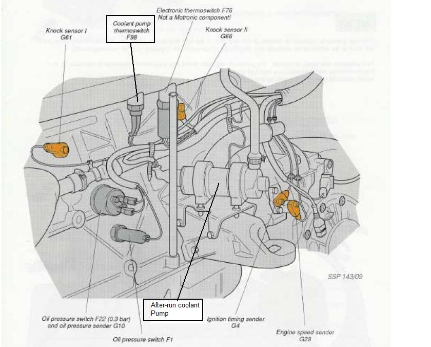
Our 20VT (3B, AAN, ABY and ADU) cooling systems include cross-flow through the head and an auxiliary after-run pump, as shown here, schematically for an AAN:
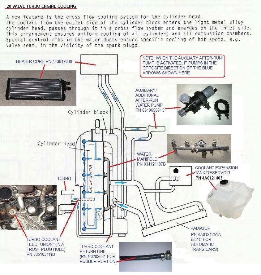
Our turbos are supplied with both pressurized oil feed and coolant lines. These lines are fed by the oil pump and the water pumps respectively when the engine is running. To help maintain the life of the turbo, there is also an auxilliary after-run pump to recirculate the coolant through the engine and turbo after the engine is shut off. However, this does not occur every time.
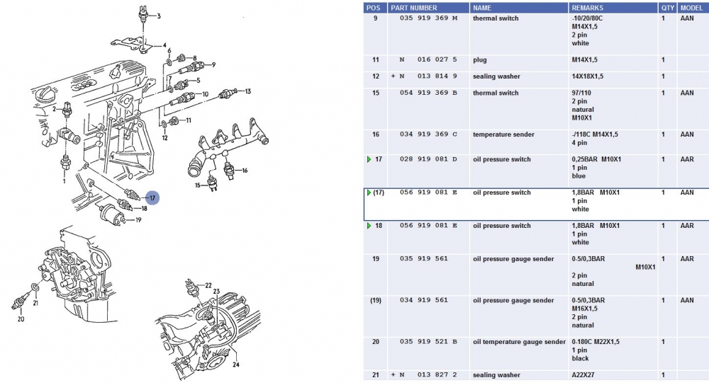
The after-run pump comes on after the engine has been shut off but only if the after-run coolant temperature ("thermal") switch F98 (PN 054919369B) located under the intake manifold, as shown below (Item 15 - thermal switch) hits 110 deg C.
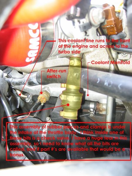
Here is the F98 After-run coolant switch in its native habitat:
The F98 switch triggers a control module (No. 324 right kick panel -see photo below) that keeps the pump on for a fixed period, e.g. 10 min. or until the temperature drops enough.
In general, the after-run pump and stage 1 of the rad fan only come on if the temperatures *AFTER* engine shut down exceed 110 C. If this happens the F98 Thermal Switch triggers the J155 After-run pump and fan control "324" module to fire up the pump and stage 1 of the rad fan until the temp drops to 97 C or 10 minutes have gone by, whichever comes first.
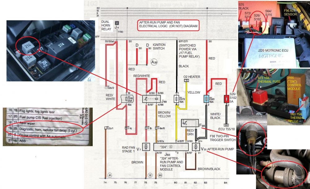
But that is skipping ahead. Backing up, the power for the after-run pump comes from the No.30 constant power bus in a red wire to the S61 fuse (a branch of that red wire also goes to the S26/102 ECU fuse that feeds pin T55/18 on the ECU (this is for the AAN, ABY/ADU different numbers but the same idea). After the S61, the wire is white/black and heads to the two pin After-run pump connector.
At the after-run pump connector, a second white/black wire branches off to the F98 thermal switch. When this switch closes at 110 C or above, the current flows to the J155 ("324") after-run pump and fan control module in a red/green wire going to pin 2/30 on the module. The module itself is energized by switch power from the J17 fuel pump relay via the S73 thermal fuse that also feeds the O2 sensor heater. From the S73, a yellow wire feeds the J155 (324) module at Pin 4/87F. This is a switched power signal so it must help the 324 determine whether the engine (and ignition) is off. If the engine is on, then even if the temps are up, then I don't think the after run-pump and/or fan will run because the 324 says, "Nope, not happening, let the water pump do its thing". (so to speak).
With the signal from the closed F98 thermal switch, the J155 (324) control module opens up a ground for the after-run pump at the module's Pin 8/87. Power flows through the V51 after-run pump in the white/black wire and out via the brown/black wire connected to the control module's Pin 8/87 (which then flows out to ground (earth) at the module's Pin 6/31).
In the meantime, the J69 (214) Stage 1 rad fan relay has been sitting with power (but no ground (earth)) from the S19 (AAN number) fuse via a red/white wire to J69 pin 2/30 and a red wire to J69 pin 5/85. When the J155 (324) gets the closed signal from the F98 thermal switch, a ground for the J69 (214) relay is opened at J69 pin 4/86. This pulls the relay on and power then flows through the S19 fuse, through the J69 (214) and out to the V7 rad fan (Stage 1) as a red/white wire from J69 Pin 8/87.
This continues on until the temp drops to 97 C and the F98 thermal switch opens again or the internal timer in the J155 (324) control module times out at 10 minutes. Presumably if the temp was not less than 110 C then, the process would repeat itself.
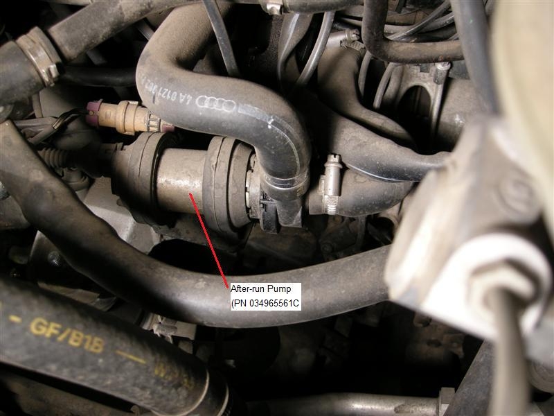
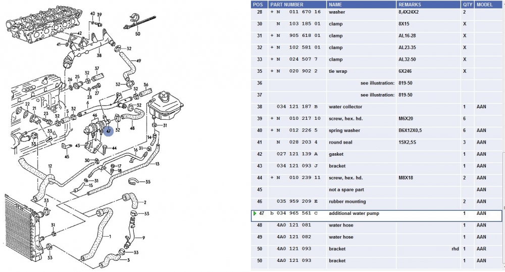
The pump itself(PN 034965561C)(Bosch PN 0-392-020-054) is fairly exposed, as shown here and here:
And just for fun, here is a photo of a Bosch 0 392 020 034 that is supposed to be plug and play:

Photo courtesy of Thuppu on the S2forum.
The after-run pump fails as shown in the photos, i.e. the plastic of the pump gets old and brittle and cracks.
Repairs do not work. The pump needs to be replaced. Inlet and outlet hoses not not seem to fail very often so I wouldn't worry about them.
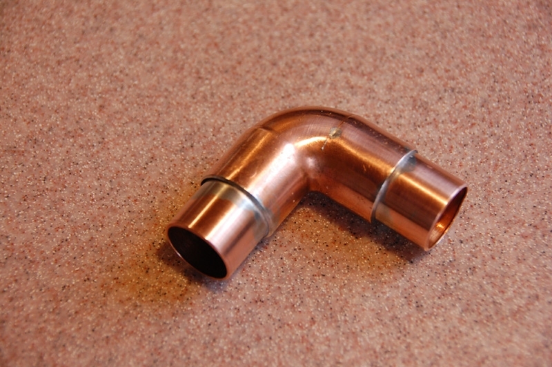
Replacement is easy. Clamp off the inlet and outlet hoses away from the pump, either using hose pinch clamps or needle nose vice grips (don't over tighten). Then remove the hose gear clamps and work the hose off of the pump. (You will only lose a bit of coolant). Remove the electrical connection and remove the pump. Replace with a 3/4" plastic 90 deg plastic hot water elbow (or a copper one if you have one) for roadside (or temporary) repair OR with a new pump. NOTE: One forum user tried a 3/4" ABS elbow but it only lasted 400 miles of highway driving before the heat killed the plastic. Copper or brass elbows or Swordfish's solution would be a better idea.
Here is a link to Swordfish's new and improved after-run pump bypass DIY to create this:
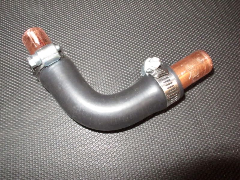
Here is Mr. Mojo's 3/4" copper pipe DIY temporary bypass shunt that he made:
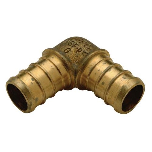
Here is Kinderutz's DIY by-pass using a 3/4" brass Pex pipe fitting:
The early VR6 cars use the same pump as the UrS, the later VR6 cars use a pump with a different electrical connector (i.e. you need to change the wiring). It has been reported that an OE UrS / Early VR6 pump could be purchased at one time from FAP99 (Tim) for $92 + shipping.
The B5 2.7tt S4 V6 after run pump (PN 078 965 561) will also work, albeit with minor modifications to the mount,as suggested in Zwoobah's August 2006 AW post:
"Dunno if this is common knowledge, but a search of the archives didn't turn up anything. My after-run pump has been leaking at the seal, and puking out a puddle of coolant every now and then. Yesterday I also had my driver's side front tire go flat while the car was sitting, meaning that I had to kneel in my suit in a puddle of coolant to change the tire. Time to replace the pump.
Today, following a tip from germantoy (Nick), I bought a B5 S4 replacement pump. This is bosch part # 0 392 020 039-030 (audi P/N 078 965 561). It replaces stock, which is bosch part # 0 392 020 054 (audi P/N 034 965 561 C). The seal is replaceable, and it cost me $125.70 from the dealer, as opposed to the $231 I was quoted for stock. Wholesale and internet are cheaper, but I didn't have time to wait.
It's a plug-n-play swap. The only difference is that the housing on the B5 pump is a little shorter, meaning that it's too short to sit in both rubber rings which hold the stock pump. 5min with an electric drill and you can punch some new holes in the stock metal mounting plate, allowing one of the rubber rings to be moved slightly and hold the B5 pump properly."
Recently (May 11, 2014), Brad (ThetaTau87) did some investigating of the VR6 and B5 options. This is what he wrote:
"In the FAQ it says that the early Corrado VR6 and UrS use the same pump (034 965 561 C.) At GVAP looking up the PN as an Audi part the online price is $198.38 ($266.63 MSRP.) As a VW part there is no online discount and the price is $266.63. A little strange that the VW part is not discounted online, but not a big deal just order it as an Audi part if you want a genuine UrS pump replacement. Millburn Audi has it even cheaper for $183.98 with the QW discount.
The B5 S4 after run pump (078 965 561) will also work, but the housing is slightly shorter and requires drilling two holes in the mounting bracket to relocate one of the rubber isolators. GVAP online price is $142.77, Millburn price is $132.41. Saving some $, but still paying dealer prices.
Then I looked this PN up at Autohaus AZ. This is where it gets interesting. The B5 S4 pump and the UrS/VR6 pump are the same price ($99.34) and are listed with the same Bosch PN 0 392 020 039.
According to Zwoobah's write up linked below the two pumps have separate Bosch PNs. UrS = 0 392 020 054 and B5 S4 = 0 392 020 039-030. It appears that AutohausAZ is selling the B5 S4 pump in place of the UrS pump. I was planning to buy the B5 S4 pump to save some cash, but it appears that even if you order the UrS pump from AutohausAZ you're going to get the B5 S4 pump in its place.
FAP99 lists the UrS and B5 S4 pumps as separate parts. The B5 S4 pump is $98.67 and the UrS pump is $195.09. Interesting that the B5 S4 pump is much cheaper than the online dealers, but the UrS pump is about the same price.
Looks like I'll be buying a B5 S4 pump from FAP99.", Brad said.
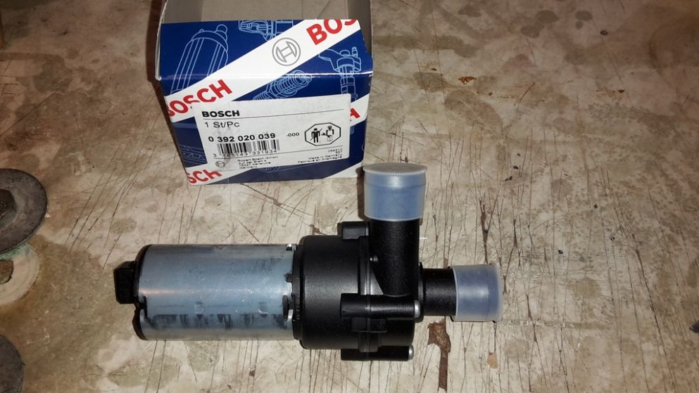
This is the B5 S4 pump:

Here is another photo of a Bosch 0392020039 which an S2 avant (ABY engine) owner received and installed after ordering a 0392020054 off eBay (a bait and switch deal). He didn't notice any difference and successfully installed the 0392020039.
On June 8, 2014 ThetaTau87 posted up some photos of his "B5 S4" (all 2.7tt's) after-run pump installed on his UrS6's AAN:
Here are the two pumps in question:
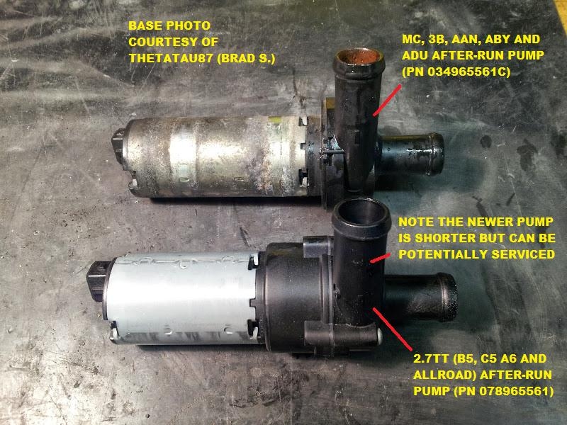
Brad says "Here the B5 pump is installed. It doesn't fit perfectly in the rubber isolators, but I was able to get it into both without relocating either of them. You can see on the pic above that the rubber isolator rings fit easily on the metal body of the original pump, but on the B5 the front isolator is nearly off the end of the metal housing. From pulling into the garage with a cool engine to closing the hood after refilling the coolant and checking for leaks was about 15 minutes. By using two hose pinch clamps the coolant lost was also minimal."
As Zwoobah had suggested, the connector was completely plug and play with the AAN harness (should be true for the 3B, ABY and ADU harnesses as well)

Sean D (quattro20v) came up with a slick trick to make the pump come on sooner. CLICK HERE
Electrical failure of either the 054919369B thermal switch or the 447965571A "324" control module can cause the after-run pump and fan to run continuously until they drain the battery dead. If this is your situation, recharge the battery and see if the pump and fan are running again. The first thing to test is the switch. Pull off the two wires on the switch (watch out for the one with red on the wire, it is 12V hot 24/7 and will short out on the block if you let it). If the pump and fan stop running, then you probably have faulty thermal switch. Test the switch for resistance across the two terminals - if you have continuity but the engine is cold or just warm, the switch is faulty and has failed closed (probably safer that failed open).
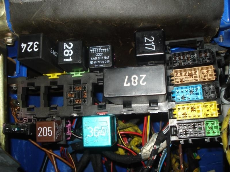
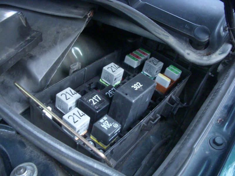
IF the pump and fan keep running for more than 10 minutes after you disconnect the thermal switch, your "324" control module is probably stuck "ON" and needs repair or replacement. Here is the location of this "324" control module (PN 447965571A) in the right hand passenger compartment kick panel (LHD UrS), Auxiliary Relay Panel 3:
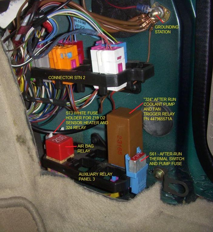
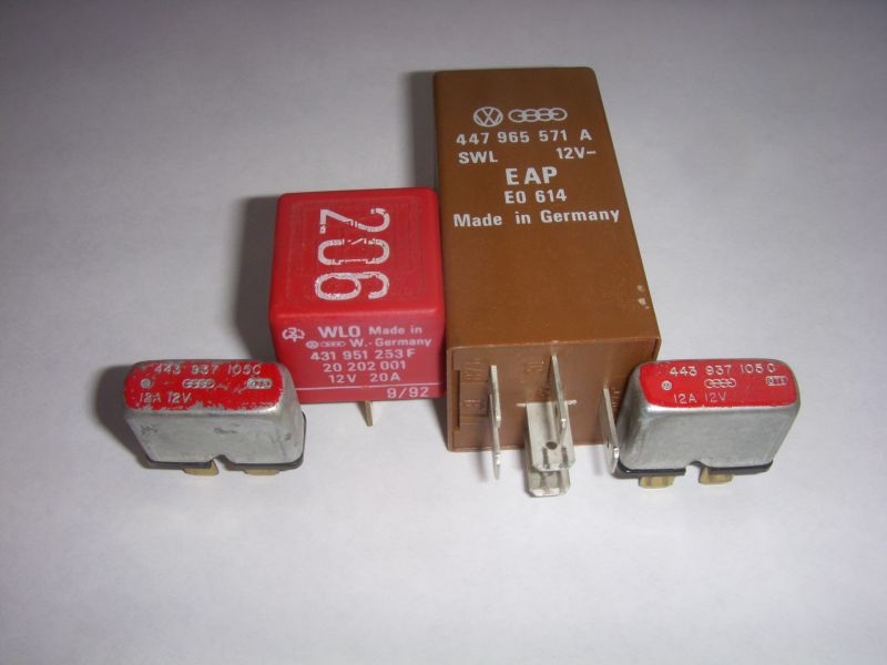
Here are the fuses and relays in that Auxiliary Relay Panel 3 holder so you can better see the PNs and amperages:
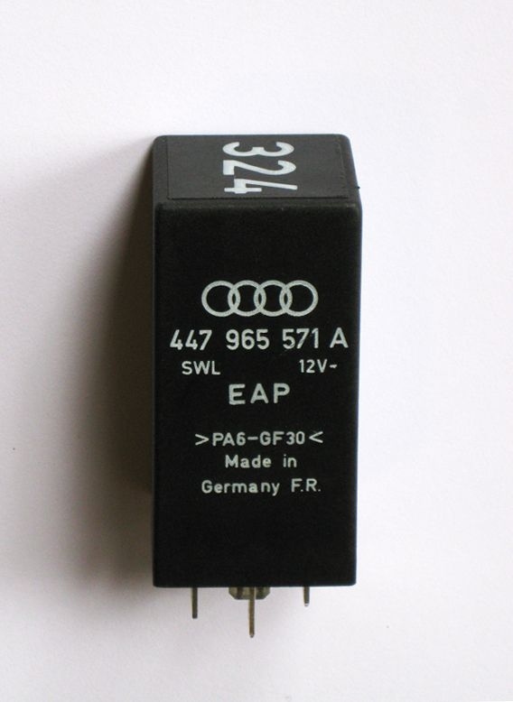
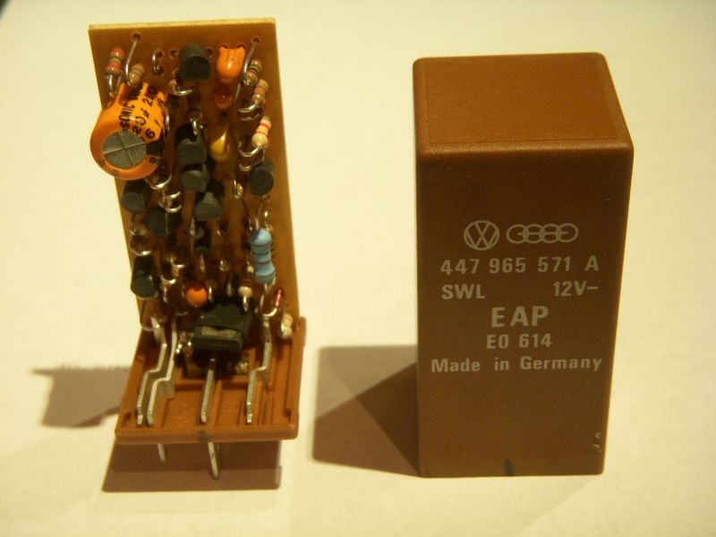
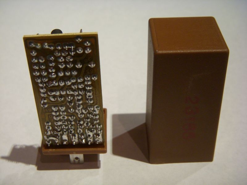
Here is a photo of the long rumoured black "324" control module, courtesy of vbmica in New Zealant (94 UrS4 RHD automatic):
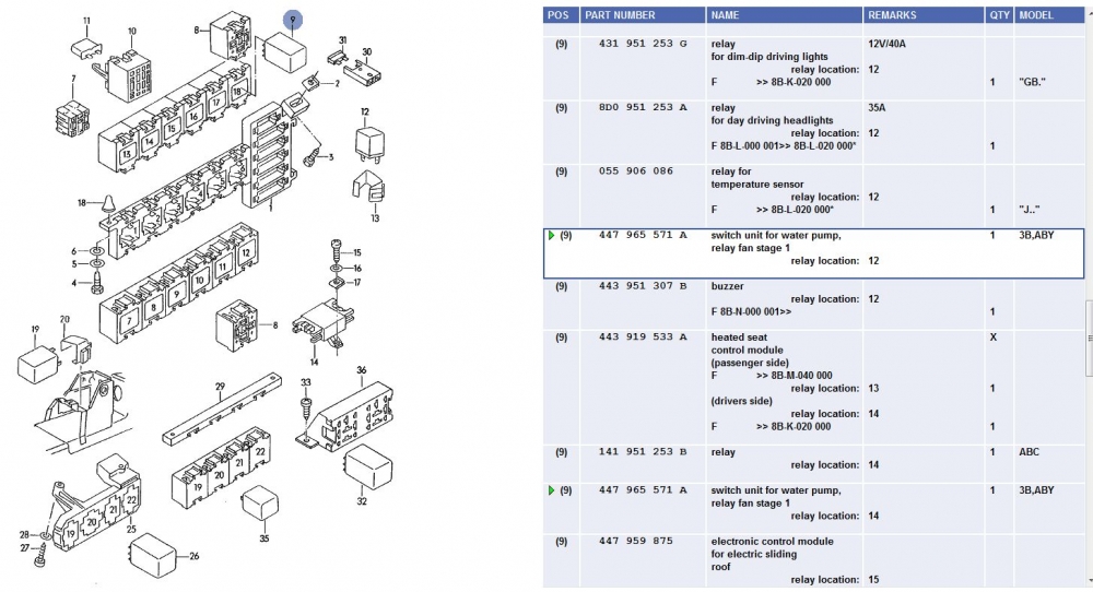
This "324" after-run pump and fan control module is common to many turbo Audis (100s, 200s, UrS4/6, S2, RS2, A4 (1.8ts) and even the RS4) as well as some 1998 and up Passats (presumably 1.8t cars) (still labled "324" and in position 3 of a 7 or 8 position relay plate), so you might be able to score one at a wrecking/breaking yard. In the S2's the control module is above the pedals as shown below:
For the S2s (and probably RS2) the 324 after-run pump control module is in position 12 in the relay panel:
I was always under the impression that the 324 failed when its relay points stuck closed. WRONG. (Merde). It is a control module (Kate says "control unit"). No mechanical contact points like a relay. All electronics. So, the only thing you might be able to check is for bad solder joints, otherwise, it is a new part (used as late as the 2001 RS4).
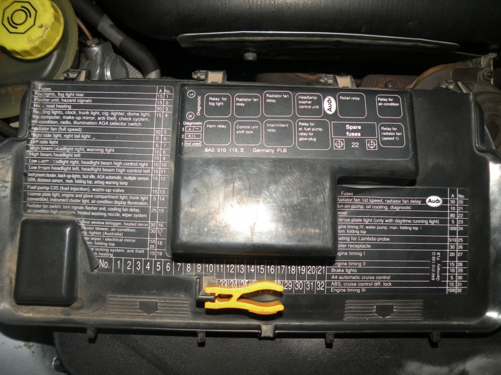
In addition to the "324" control module that brings the after-run pump on, for the 93 spec and newer UrS cars, there is also a "214" relay that brings the radiator fan on for that 10 minute period. For the 93 and newer UrS4s and the UrS6s, that "214" relay is in relay position No. 1 in the relay and fuse box under the hood/bonnet. Recently, vbmica posted a photo of a sticker that maps out that 214 relay in postion 1 as the "delay time cooling fan". Bentley calls it the "After-run coolant fan control (FC) relay, J69":
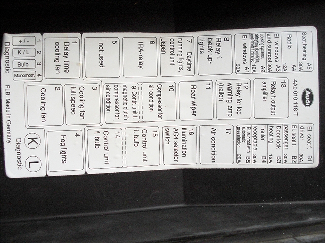
Photo courtesy of vbmica.
This photo (from Canadian 93 UrS4 with DRLs) shows the 214 in position 1 (and another 214 in position 7 for the DRLs) (NOTE: the 92 spec UrS4s do NOT have a 214 relay in position 1, implying that both after-run coolant pump and rad fan are powered through the 324 (which might cause them to weld their contacts "ON")).
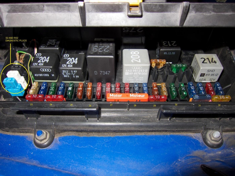
For the B3/B4 S2s and RS2s, the "214" Fan Speed 1 relay that is triggered by the "324" control module is in the under hood/bonnet fuse/relay box, to the right of the spare fuses, as shown in these two photos:
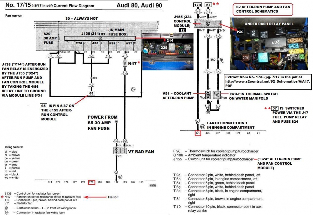
Note: I have created the diagram below for the S2s and RS2s based on S2Central's S2 wiring pdf . In doing so, I discovered two things:
1. The C4 UrS J69 (214) fan relay is called a J138 on the S2.
2. There is a resistor (N47) in series with the fan in Stage 1 that my C4 UrS diagram did not show.
As a result, if a S2 after-run fan is not coming on but the V51 After-run pump is coming on, you need to check the S5 fuse, the S20 fuse, and the N47.
Note: There is possibility to accidentally swap the black N71 ISV connector and the black after-run pump connectors due to the general proximity of the 4 pin-connectors around/under the AAN intake manifold as shown below and discussed HERE:
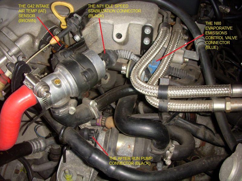
When in doubt check the wires (pull back the rubber grommet on the connector so you can see the wire colours):
1. The G42 intake air temp sensor (IAT) is a two pin connector. Should be a brown connector on the harness side. The original G42 IATs (PN 034905379B) were brown so matching brown to brown is a no brainer. However, later G42 IATs might be black. But the connector should still be brown. When in doubt, on an AAN, check the wire colours: the G42 IAT wire colours are Brown/Blue from the T55/44 (ECU pin 44) and a Green/Blk wire that goes to ground (somewhere in the engine harness).
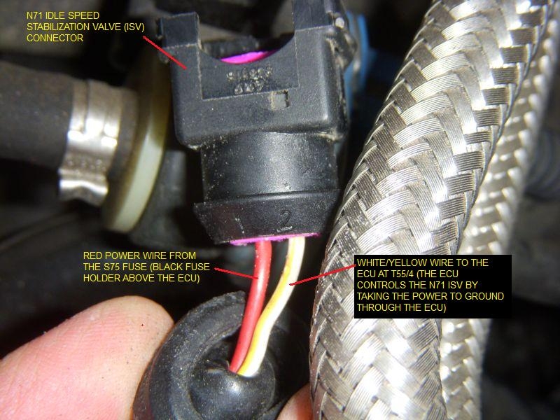
2. The N71 Idle speed control valve (ISV) is a black two pin. It has a white/yellow wire from T55/4 (to control the ISV location) and a red power wire that comes through the S75 fuse.
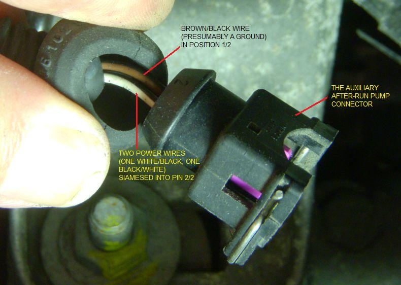
3. The after-run pump. It has three wires in a black 2 pin connector. A white/blk and a blk/white wire (presumably two 12V relayed power sources) are siamesed into one pin and a third wire, brown/black (presumably a ground) in the second pin.
However, this is easily checked by confirming the wire colours before connecting.
N71 Connector:
Here is the AAN after-run pump connector (black, unlabled, in the lower middle of the photo):

And here are the wire colours in the black after-run pump connector:
On an AAN, and I would guess on an ABY, it might also possible to swap the 2 pin connector on the ISV and the IAT. They are the same size and the wire lengths make it possible to make this minor, but important, mistake. It also looks potentially possible to swap the after-run pump into the wrong position in an AAN but I doubt that it is physically possible in an ABY situation. Marintjs on the S2Forum says "Yes, on an ABY, the IAT plug won't reach to the after-run pump, but on the AAN the wiring to both sensors are a very similar length". So be aware folks. (We need more "wares"). ;>)
Thanks to those who posted images to http://12v.org/urs
Hope that helps
Our turbos are supplied with both pressurized oil feed and coolant lines. These lines are fed by the oil pump and the water pumps respectively when the engine is running. To help maintain the life of the turbo, there is also an auxilliary after-run pump to recirculate the coolant through the engine and turbo after the engine is shut off. However, this does not occur every time.
The after-run pump comes on after the engine has been shut off but only if the after-run coolant temperature ("thermal") switch F98 (PN 054919369B) located under the intake manifold, as shown below (Item 15 - thermal switch) hits 110 deg C.
Here is the F98 After-run coolant switch in its native habitat:
The F98 switch triggers a control module (No. 324 right kick panel -see photo below) that keeps the pump on for a fixed period, e.g. 10 min. or until the temperature drops enough.
In general, the after-run pump and stage 1 of the rad fan only come on if the temperatures *AFTER* engine shut down exceed 110 C. If this happens the F98 Thermal Switch triggers the J155 After-run pump and fan control "324" module to fire up the pump and stage 1 of the rad fan until the temp drops to 97 C or 10 minutes have gone by, whichever comes first.
But that is skipping ahead. Backing up, the power for the after-run pump comes from the No.30 constant power bus in a red wire to the S61 fuse (a branch of that red wire also goes to the S26/102 ECU fuse that feeds pin T55/18 on the ECU (this is for the AAN, ABY/ADU different numbers but the same idea). After the S61, the wire is white/black and heads to the two pin After-run pump connector.
At the after-run pump connector, a second white/black wire branches off to the F98 thermal switch. When this switch closes at 110 C or above, the current flows to the J155 ("324") after-run pump and fan control module in a red/green wire going to pin 2/30 on the module. The module itself is energized by switch power from the J17 fuel pump relay via the S73 thermal fuse that also feeds the O2 sensor heater. From the S73, a yellow wire feeds the J155 (324) module at Pin 4/87F. This is a switched power signal so it must help the 324 determine whether the engine (and ignition) is off. If the engine is on, then even if the temps are up, then I don't think the after run-pump and/or fan will run because the 324 says, "Nope, not happening, let the water pump do its thing". (so to speak).
With the signal from the closed F98 thermal switch, the J155 (324) control module opens up a ground for the after-run pump at the module's Pin 8/87. Power flows through the V51 after-run pump in the white/black wire and out via the brown/black wire connected to the control module's Pin 8/87 (which then flows out to ground (earth) at the module's Pin 6/31).
In the meantime, the J69 (214) Stage 1 rad fan relay has been sitting with power (but no ground (earth)) from the S19 (AAN number) fuse via a red/white wire to J69 pin 2/30 and a red wire to J69 pin 5/85. When the J155 (324) gets the closed signal from the F98 thermal switch, a ground for the J69 (214) relay is opened at J69 pin 4/86. This pulls the relay on and power then flows through the S19 fuse, through the J69 (214) and out to the V7 rad fan (Stage 1) as a red/white wire from J69 Pin 8/87.
This continues on until the temp drops to 97 C and the F98 thermal switch opens again or the internal timer in the J155 (324) control module times out at 10 minutes. Presumably if the temp was not less than 110 C then, the process would repeat itself.
The pump itself(PN 034965561C)(Bosch PN 0-392-020-054) is fairly exposed, as shown here and here:
And just for fun, here is a photo of a Bosch 0 392 020 034 that is supposed to be plug and play:
Photo courtesy of Thuppu on the S2forum.
The after-run pump fails as shown in the photos, i.e. the plastic of the pump gets old and brittle and cracks.
Repairs do not work. The pump needs to be replaced. Inlet and outlet hoses not not seem to fail very often so I wouldn't worry about them.
Replacement is easy. Clamp off the inlet and outlet hoses away from the pump, either using hose pinch clamps or needle nose vice grips (don't over tighten). Then remove the hose gear clamps and work the hose off of the pump. (You will only lose a bit of coolant). Remove the electrical connection and remove the pump. Replace with a 3/4" plastic 90 deg plastic hot water elbow (or a copper one if you have one) for roadside (or temporary) repair OR with a new pump. NOTE: One forum user tried a 3/4" ABS elbow but it only lasted 400 miles of highway driving before the heat killed the plastic. Copper or brass elbows or Swordfish's solution would be a better idea.
Here is a link to Swordfish's new and improved after-run pump bypass DIY to create this:
Here is Mr. Mojo's 3/4" copper pipe DIY temporary bypass shunt that he made:
Here is Kinderutz's DIY by-pass using a 3/4" brass Pex pipe fitting:
The early VR6 cars use the same pump as the UrS, the later VR6 cars use a pump with a different electrical connector (i.e. you need to change the wiring). It has been reported that an OE UrS / Early VR6 pump could be purchased at one time from FAP99 (Tim) for $92 + shipping.
The B5 2.7tt S4 V6 after run pump (PN 078 965 561) will also work, albeit with minor modifications to the mount,as suggested in Zwoobah's August 2006 AW post:
"Dunno if this is common knowledge, but a search of the archives didn't turn up anything. My after-run pump has been leaking at the seal, and puking out a puddle of coolant every now and then. Yesterday I also had my driver's side front tire go flat while the car was sitting, meaning that I had to kneel in my suit in a puddle of coolant to change the tire. Time to replace the pump.
Today, following a tip from germantoy (Nick), I bought a B5 S4 replacement pump. This is bosch part # 0 392 020 039-030 (audi P/N 078 965 561). It replaces stock, which is bosch part # 0 392 020 054 (audi P/N 034 965 561 C). The seal is replaceable, and it cost me $125.70 from the dealer, as opposed to the $231 I was quoted for stock. Wholesale and internet are cheaper, but I didn't have time to wait.
It's a plug-n-play swap. The only difference is that the housing on the B5 pump is a little shorter, meaning that it's too short to sit in both rubber rings which hold the stock pump. 5min with an electric drill and you can punch some new holes in the stock metal mounting plate, allowing one of the rubber rings to be moved slightly and hold the B5 pump properly."
Recently (May 11, 2014), Brad (ThetaTau87) did some investigating of the VR6 and B5 options. This is what he wrote:
"In the FAQ it says that the early Corrado VR6 and UrS use the same pump (034 965 561 C.) At GVAP looking up the PN as an Audi part the online price is $198.38 ($266.63 MSRP.) As a VW part there is no online discount and the price is $266.63. A little strange that the VW part is not discounted online, but not a big deal just order it as an Audi part if you want a genuine UrS pump replacement. Millburn Audi has it even cheaper for $183.98 with the QW discount.
The B5 S4 after run pump (078 965 561) will also work, but the housing is slightly shorter and requires drilling two holes in the mounting bracket to relocate one of the rubber isolators. GVAP online price is $142.77, Millburn price is $132.41. Saving some $, but still paying dealer prices.
Then I looked this PN up at Autohaus AZ. This is where it gets interesting. The B5 S4 pump and the UrS/VR6 pump are the same price ($99.34) and are listed with the same Bosch PN 0 392 020 039.
According to Zwoobah's write up linked below the two pumps have separate Bosch PNs. UrS = 0 392 020 054 and B5 S4 = 0 392 020 039-030. It appears that AutohausAZ is selling the B5 S4 pump in place of the UrS pump. I was planning to buy the B5 S4 pump to save some cash, but it appears that even if you order the UrS pump from AutohausAZ you're going to get the B5 S4 pump in its place.
FAP99 lists the UrS and B5 S4 pumps as separate parts. The B5 S4 pump is $98.67 and the UrS pump is $195.09. Interesting that the B5 S4 pump is much cheaper than the online dealers, but the UrS pump is about the same price.
Looks like I'll be buying a B5 S4 pump from FAP99.", Brad said.
This is the B5 S4 pump:
Here is another photo of a Bosch 0392020039 which an S2 avant (ABY engine) owner received and installed after ordering a 0392020054 off eBay (a bait and switch deal). He didn't notice any difference and successfully installed the 0392020039.
On June 8, 2014 ThetaTau87 posted up some photos of his "B5 S4" (all 2.7tt's) after-run pump installed on his UrS6's AAN:
Here are the two pumps in question:
Brad says "Here the B5 pump is installed. It doesn't fit perfectly in the rubber isolators, but I was able to get it into both without relocating either of them. You can see on the pic above that the rubber isolator rings fit easily on the metal body of the original pump, but on the B5 the front isolator is nearly off the end of the metal housing. From pulling into the garage with a cool engine to closing the hood after refilling the coolant and checking for leaks was about 15 minutes. By using two hose pinch clamps the coolant lost was also minimal."
As Zwoobah had suggested, the connector was completely plug and play with the AAN harness (should be true for the 3B, ABY and ADU harnesses as well)
Sean D (quattro20v) came up with a slick trick to make the pump come on sooner. CLICK HERE
Electrical failure of either the 054919369B thermal switch or the 447965571A "324" control module can cause the after-run pump and fan to run continuously until they drain the battery dead. If this is your situation, recharge the battery and see if the pump and fan are running again. The first thing to test is the switch. Pull off the two wires on the switch (watch out for the one with red on the wire, it is 12V hot 24/7 and will short out on the block if you let it). If the pump and fan stop running, then you probably have faulty thermal switch. Test the switch for resistance across the two terminals - if you have continuity but the engine is cold or just warm, the switch is faulty and has failed closed (probably safer that failed open).
IF the pump and fan keep running for more than 10 minutes after you disconnect the thermal switch, your "324" control module is probably stuck "ON" and needs repair or replacement. Here is the location of this "324" control module (PN 447965571A) in the right hand passenger compartment kick panel (LHD UrS), Auxiliary Relay Panel 3:
Here are the fuses and relays in that Auxiliary Relay Panel 3 holder so you can better see the PNs and amperages:
Here is a photo of the long rumoured black "324" control module, courtesy of vbmica in New Zealant (94 UrS4 RHD automatic):
This "324" after-run pump and fan control module is common to many turbo Audis (100s, 200s, UrS4/6, S2, RS2, A4 (1.8ts) and even the RS4) as well as some 1998 and up Passats (presumably 1.8t cars) (still labled "324" and in position 3 of a 7 or 8 position relay plate), so you might be able to score one at a wrecking/breaking yard. In the S2's the control module is above the pedals as shown below:
For the S2s (and probably RS2) the 324 after-run pump control module is in position 12 in the relay panel:
I was always under the impression that the 324 failed when its relay points stuck closed. WRONG. (Merde). It is a control module (Kate says "control unit"). No mechanical contact points like a relay. All electronics. So, the only thing you might be able to check is for bad solder joints, otherwise, it is a new part (used as late as the 2001 RS4).
In addition to the "324" control module that brings the after-run pump on, for the 93 spec and newer UrS cars, there is also a "214" relay that brings the radiator fan on for that 10 minute period. For the 93 and newer UrS4s and the UrS6s, that "214" relay is in relay position No. 1 in the relay and fuse box under the hood/bonnet. Recently, vbmica posted a photo of a sticker that maps out that 214 relay in postion 1 as the "delay time cooling fan". Bentley calls it the "After-run coolant fan control (FC) relay, J69":
Photo courtesy of vbmica.
This photo (from Canadian 93 UrS4 with DRLs) shows the 214 in position 1 (and another 214 in position 7 for the DRLs) (NOTE: the 92 spec UrS4s do NOT have a 214 relay in position 1, implying that both after-run coolant pump and rad fan are powered through the 324 (which might cause them to weld their contacts "ON")).
For the B3/B4 S2s and RS2s, the "214" Fan Speed 1 relay that is triggered by the "324" control module is in the under hood/bonnet fuse/relay box, to the right of the spare fuses, as shown in these two photos:
Note: I have created the diagram below for the S2s and RS2s based on S2Central's S2 wiring pdf . In doing so, I discovered two things:
1. The C4 UrS J69 (214) fan relay is called a J138 on the S2.
2. There is a resistor (N47) in series with the fan in Stage 1 that my C4 UrS diagram did not show.
As a result, if a S2 after-run fan is not coming on but the V51 After-run pump is coming on, you need to check the S5 fuse, the S20 fuse, and the N47.
Note: There is possibility to accidentally swap the black N71 ISV connector and the black after-run pump connectors due to the general proximity of the 4 pin-connectors around/under the AAN intake manifold as shown below and discussed HERE:
When in doubt check the wires (pull back the rubber grommet on the connector so you can see the wire colours):
1. The G42 intake air temp sensor (IAT) is a two pin connector. Should be a brown connector on the harness side. The original G42 IATs (PN 034905379B) were brown so matching brown to brown is a no brainer. However, later G42 IATs might be black. But the connector should still be brown. When in doubt, on an AAN, check the wire colours: the G42 IAT wire colours are Brown/Blue from the T55/44 (ECU pin 44) and a Green/Blk wire that goes to ground (somewhere in the engine harness).
2. The N71 Idle speed control valve (ISV) is a black two pin. It has a white/yellow wire from T55/4 (to control the ISV location) and a red power wire that comes through the S75 fuse.
3. The after-run pump. It has three wires in a black 2 pin connector. A white/blk and a blk/white wire (presumably two 12V relayed power sources) are siamesed into one pin and a third wire, brown/black (presumably a ground) in the second pin.
However, this is easily checked by confirming the wire colours before connecting.
N71 Connector:
Here is the AAN after-run pump connector (black, unlabled, in the lower middle of the photo):
And here are the wire colours in the black after-run pump connector:
On an AAN, and I would guess on an ABY, it might also possible to swap the 2 pin connector on the ISV and the IAT. They are the same size and the wire lengths make it possible to make this minor, but important, mistake. It also looks potentially possible to swap the after-run pump into the wrong position in an AAN but I doubt that it is physically possible in an ABY situation. Marintjs on the S2Forum says "Yes, on an ABY, the IAT plug won't reach to the after-run pump, but on the AAN the wiring to both sensors are a very similar length". So be aware folks. (We need more "wares"). ;>)
Thanks to those who posted images to http://12v.org/urs
Hope that helps

 -
-  -
-

You must be registered and logged in to post. Please select an option: |
| All messages | Search Forums | Return to UrS4/UrS6/S2/RS2 |
 Your Privacy Choices